Draw the circuit diagram of full adder with its truth table and working [diagram] logic diagram 4 bit adder 10+ adder circuit diagram
For those of you wondering how code becomes "ones and zeros
Bit adder implementation addition logic using gates bits adders numbers make calculator circuit two schematic carry ripple add input electronics Full-adder circuit, the schematic diagram and how it works – deeptronic Adder circuitverse
Adder bit circuit subtractor ripple carry logic diagram using project only digital its computing learn let build single indie electronics
4 bit parallel adder circuit diagramAdder bit binary instructables Evolvable hardware lab 1Adder bit circuit half make logic diagram comparator gates first electronics questions cout second there only solved puzzle connecting which.
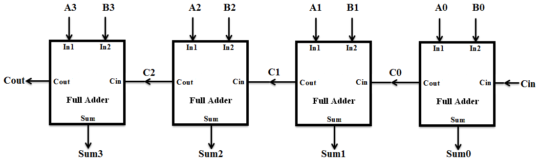
Solved 1. build and test a 1-bit full adder in multisinm,4 bit binary adder circuit diagram For those of you wondering how code becomes "ones and zeros4 bit adder circuit diagram.

Adder carry circuit sum logic simplified electronics output outputs two implementation tutorial combinational circuits both shows below figure
Logic gatesAdder bit logisim using circuit ripple carry build help ta sub ask create re Block diagram of basic full adder circuitAdder circuit construction binary circuits qiskit sourav gupta.
Adder circuit combinational ha sequentialWhat is half adder and full adder circuit? 2-bit adder implementationAdder bit using circuit adders half four circuits implementation watson single just box latech edu.
Cs 3410 spring 2018 lab 1
Adder additionneur binaire zpag electroniques gate sumBinary adder circuit / circuit additionneur binaire Adder circuit diagram schematic works figureCombinational and sequential design of a 4-bit adder. (a) ha circuit.
2 bit full adder subtractor circuit diagram schematicAdder xor rangkaian transistor ripple pengertian kombinasi Adder cmos soiCs3410 fall 2015 lab 0.

Adder bit circuit lab evolvable hardware
Adder bit circuitverse[diagram] circuit diagram 2 bit full adder Adder bit ripple carry verilog four block adders cascading diagram beginners figure formedFull adder circuit: theory, truth table & construction.
Full adder equationCircuit diagram of a one-bit full adder using the proposed technique in Verilog for beginners: 4-bit carry ripple adderFull adder.

4 bit adder circuit diagram
2 bit adder circuit diagramDale circuit: 4 bit full adder circuit diagram examples Full adder circuit diagramAdder circuit diagram schematic circuitglobe representation robhosking.
1 bit full adderAdder circuit circuitverse Adder circuit diagram geeksforgeeks bit subtractor binary sourceLet's learn computing: 4 bit adder/subtractor circuit.

Adder bit test circuit build chegg problem solved
Adder circuit two add logic gate addition subtractor delay combinational numbers half gates binary find table adding circuits code truth .
.


What is Half Adder and Full Adder Circuit? - Circuit Diagram & Truth

Binary adder circuit / Circuit additionneur binaire

logic gates - How to make 2 bit or more half adder circuit - Electrical

Evolvable Hardware Lab 1 - The Lab Book Pages

Solved 1. Build and test a 1-bit full adder in Multisinm, | Chegg.com

Dale Circuit: 4 Bit Full Adder Circuit Diagram Examples